
This article provides a technical explanation of STT-MRAM principles, covering the MTJ structure, write/read mechanisms based on spin-transfer torque, scaling challenges, and future application potential.
What Is STT-MRAM? Basic Structure and Positioning
Differences Between MRAM as a Whole and the STT Method
MRAM (Magnetoresistive Random Access Memory) is a type of non-volatile memory that records information using magnetic states instead of electric charge. Among its variants, the STT (Spin-Transfer Torque) method differs from conventional Toggle MRAM in that it switches magnetization using spin-polarized current rather than magnetic fields. The Toggle method requires multiple wiring lines, which limits scalability, whereas the STT method enables read/write operations using a single bit line, making it easier to achieve higher integration density and enabling adoption in mobile devices and IoT applications. For this reason, STT-MRAM is attracting attention as a leading candidate for next-generation non-volatile memory.
Overview of MTJ + 1T Configuration
The basic structure of an STT-MRAM cell consists of an MTJ (Magnetic Tunnel Junction) and one selection transistor (1T). The MTJ is composed of two ferromagnetic layers separated by an insulating layer, and the ease of tunneling current flow changes depending on whether the magnetization directions are aligned or not, enabling the storage of binary information (0 and 1). The transistor controls selective write and read operations, allowing the structure to be implemented as an integrated circuit. The 1T-MTJ configuration ensures area efficiency comparable to conventional memory cells while enabling a non-volatile device architecture.
Advantages in Non-Volatility, Endurance, and Speed
STT-MRAM retains data even when power is turned off and also offers excellent write endurance. While conventional flash memory typically supports around 10^5 write cycles, STT-MRAM can achieve endurance exceeding 10^14 cycles. In addition, its read/write speed is on the order of tens of nanoseconds, comparable to DRAM, making it suitable for high-speed applications such as cache memory. Furthermore, since it does not consume power in standby, it contributes to power savings in IoT and mobile devices. These characteristics position STT-MRAM as a promising core memory technology for the future.
Structure and Role of the Magnetic Tunnel Junction (MTJ)
Configuration of Fixed Layer, Free Layer, and Tunnel Barrier
The MTJ (Magnetic Tunnel Junction) is the core storage element of STT-MRAM. It consists of two ferromagnetic layers and an insulating layer (typically MgO) sandwiched between them. The upper “free layer” changes its magnetization direction during write operations, while the lower “fixed layer” maintains a constant magnetization direction. The tunnel barrier is an extremely thin insulator through which electrons can pass via quantum tunneling. When the magnetization of the free and fixed layers is parallel, current flows more easily; when antiparallel, current flow is reduced, and this resistance difference is used to represent binary data (“0” and “1”).
Resistance Variation and the TMR Effect
The resistance of the MTJ varies depending on the relative magnetization directions of the free and fixed layers, a phenomenon known as the TMR (Tunnel Magnetoresistance) effect. Specifically, when the magnetizations are parallel, the MTJ exhibits a low-resistance state (logic “1”), while when antiparallel, it exhibits a high-resistance state (logic “0”). By utilizing this resistance difference, external circuits can accurately detect the stored state during read operations. With the adoption of MgO barriers, TMR ratios exceeding 200% have become achievable, significantly contributing to the reliability and speed of STT-MRAM. This clear resistance distinction underpins accurate readout performance.
In-Plane vs Perpendicular Magnetization (p-MTJ)
There are two main types of MTJ magnetization configurations. One is the in-plane MTJ, where magnetization is parallel to the film surface, and the other is the perpendicular MTJ (p-MTJ), where magnetization is oriented perpendicular to the film surface. In recent years, p-MTJ has become the mainstream due to its advantages in high-density integration and reduced power consumption. Because p-MTJ offers higher spin injection efficiency, it enables magnetization switching with lower write current, making it well suited for scaling and 3D structures. It also provides higher thermal stability than in-plane MTJ, making it suitable for embedded systems and industrial applications that require reliable data retention.
Write and Read Principles of Spin-Transfer Torque (STT)
Magnetization Switching by Spin-Polarized Current
The core of STT-MRAM write operation is spin-transfer torque (STT), a phenomenon in which spin-polarized current is used to control the magnetization direction of the free layer. As current passes through the MTJ, electron spins are polarized by the fixed layer and transfer spin angular momentum to the free layer, causing magnetization reversal. Compared to the external magnetic fields used in conventional MRAM, STT is better suited for fine structures and offers lower power consumption. Although a certain current density is required to induce switching, ongoing material optimization is reducing the required write current.
Read Operation: MTJ Resistance Sensing
The read operation is performed by detecting differences in MTJ resistance as a voltage signal. A relatively small read current is applied to the STT-MRAM cell, and the resistance changes depending on the relative orientation of the free and fixed layers. This resistance difference is detected by sensing circuits and decoded as a logical “0” or “1.” The read current is significantly smaller than the write current and must be low enough not to disturb the magnetic state of the cell. With high TMR ratios and advanced sensing techniques, STT-MRAM achieves fast and reliable read operations.
Relationship Between Write Current and Scaling
Reducing write current is a critical challenge for scaling STT-MRAM. As device dimensions shrink, cell area decreases, and configurations that require high current can lead to wiring current capacity becoming a bottleneck. For this reason, structures such as p-MTJ, which suppress write current, are attracting attention. Further improvements in write efficiency are being pursued through material selection, optimization of magnetic anisotropy in the free layer, and the use of low spin-relaxation materials. As a result, STT-MRAM can achieve more compact and power-efficient configurations, enabling its deployment in next-generation mobile devices and edge devices.
Challenges and Practical Outlook for STT-MRAM
High Write Current Requirements and Thermal Fluctuations
While STT-MRAM offers high performance and reliability, one of its key challenges is the relatively large current required for write operations. This issue is becoming more significant as scaling progresses, since increased current density may affect device reliability and lifetime. Thermal fluctuations can also destabilize the magnetization state of the free layer. In high-temperature environments, data retention may degrade, making improved thermal stability essential for industrial and automotive applications. To address these challenges, active research is being conducted on magnetic anisotropy materials and new structural designs.
Technical Challenges in Testing and Manufacturing
The manufacturing process of STT-MRAM requires advanced process control, including MTJ deposition, etching, and alignment precision. The uniformity of the MgO insulating layer and precise control of magnetization direction are some particularly critical factors that directly impact device performance and yield. Circuit design is also required to mitigate variations in write behavior and interference between cells. In addition, testing STT-MRAM differs from conventional semiconductors, as evaluation of magnetic properties is required, necessitating specialized test methods and equipment. Overcoming these challenges requires an integrated approach combining materials, process technology, and circuit design.
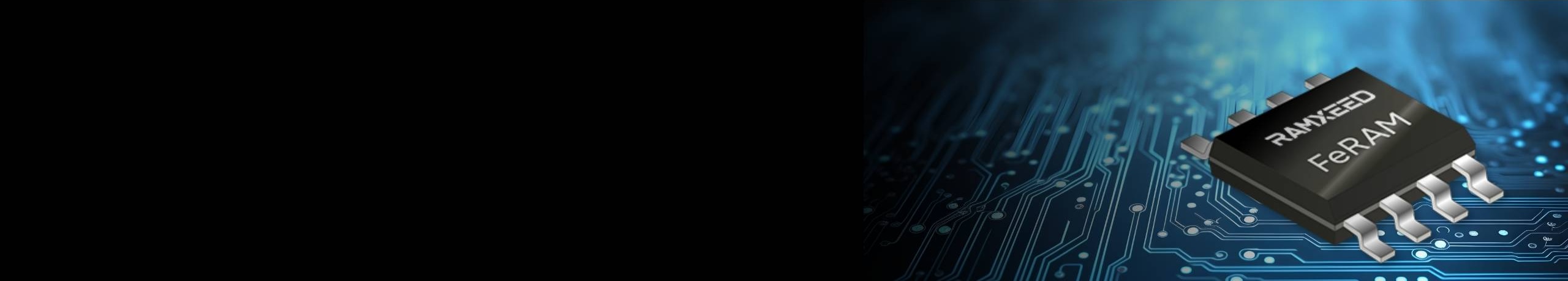
Reliability Issues of Standalone STT-MRAM and Advantages of FeRAM
In recent years, STT-MRAM has been expected to be used in CPU caches, SSD buffer memory, and embedded devices due to its high speed and non-volatility. However, as a standalone memory, the large current required for writing and the resulting high current density remain major challenges. In particular, while memory arrays can be distributed in chips that integrate memory and logic, the array is concentrated in standalone memory, resulting in consistently high current density. This can lead to degradation phenomena such as E-migration (E-mig), seriously impacting long-term reliability. On the other hand, FeRAM consumes extremely low current during writing, fundamentally avoiding current density problems. Furthermore, it does not generate stress due to high current, resulting in very high E-mig and thermal stress resistance, virtually eliminating reliability concerns. Considering all of the above, choosing FeRAM over STT-MRAM for standalone memory applications offers advantages in terms of safety and reliability.
RAMXEED FeRAM Product Lineup
FeRAM Product List|RAMXEED
RAMXEED ReRAM Product Lineup
ReRAM Product List|RAMXEED