Fundamentals of Mixed-Signal IC Design: From Noise Mitigation to Applications
This guide provides a comprehensive overview of mixed-signal ICs, the challenges and countermeasures faced during design such as noise and crosstalk, the basics of domain isolation and ground design in PCB layout, the latest technological trends, and available resources.
Introduction: An Overview of Mixed-Signal ICs
Mixed-signal ICs are integrated circuits that combine analog and digital signal processing functions onto a single semiconductor chip. The analog portion handles continuous physical quantities such as voltage and current, while the digital portion logically controls, calculates, and records them. This integration enables circuit size reduction, miniaturization, power saving, and high speed. Typical applications include smartphone communication functions, sensor processing in automotive control units, and signal analysis in medical devices. Understanding the fundamental elements necessary to maximize performance, given the design challenges arising from the coexistence of analog and digital, is crucial.
What is a Mixed-Signal IC?
A mixed-signal IC integrates the conversion and processing of input and output signals by placing analog and digital circuits, which have different properties, on the same silicon. The analog circuit converts, amplifies, and filters external signals, while the digital circuit processes that data using logical operations and control algorithms. Single-chip integration shortens signal paths, reduces noise, and lowers power consumption and latency. It is a core technology that enables both performance and efficiency in modern electronic devices where multi-functionality and high speed are demanded.
The Roles of Digital and Analog Circuits
Analog circuits accurately handle continuous signals from sensors and antennas, performing amplification and bandwidth limiting as needed. An ADC (Analog-to-Digital Converter) converts these signals to digital signals, and digital circuits perform control and calculations. A DAC (Digital-to-Analog Converter) is required to return the control results to the physical system. The digital portion excels at flexible function changes and complex calculations, while the analog portion is suitable for high-sensitivity and high-precision signal processing. This division of roles allows for the efficient implementation of diverse functions.
Key Components
Typical components include ADCs, DACs, PLLs (Phase-Locked Loops), power management circuits, and RF CMOS blocks. The ADC converts analog signals to digital, and the DAC performs the reverse conversion. The PLL generates a stable clock, ensuring synchronization between circuits. The power management circuit supplies appropriate voltage and current to each block, supporting stable operation. RF CMOS enables wireless communication and high-frequency signal processing. These components work together to realize a multi-functional and highly efficient system.
Main Application Fields
IoT devices integrate sensor measurement and wireless communication while maintaining low power consumption, enabling long-term battery operation. In the automotive sector, stable operation under harsh conditions such as temperature and vibration, and real-time responsiveness are essential. In medical devices, high-precision signal processing for electrocardiograms and ultrasounds is indispensable. In the communications sector, high-frequency signal processing and high-speed digital control are integrated, contributing to improved performance in network equipment and mobile devices. Common to all fields is improved signal quality and space saving through the integration of analog and digital.
Main Challenges and Basic Countermeasures During Design
Differences in operating characteristics between analog and digital circuits make the system susceptible to noise interference, crosstalk, and power supply quality degradation. Noise originates from digital switching operations and power supply fluctuations, impairing analog accuracy. To suppress this, it is necessary to physically separate the analog and digital domains and implement return path control and appropriate decoupling. Crosstalk occurs through wiring and board structure, so signal path isolation and impedance management are effective. Power supply quality can be improved with hierarchical decoupling and dedicated power supply domains.
Noise and Ground Design
To minimize noise interference, it is necessary to ensure a low-impedance, continuous ground plane and systematically control the return paths of analog and digital signals. Completely separating the grounds can lengthen the return paths, potentially degrading high-frequency characteristics. Therefore, many designs employ single-point grounding or zoning to ensure stable return paths while suppressing high-frequency component interference. Planning the ground structure in the early stages of design directly contributes to the stability of the final performance.
Simulation and Verification
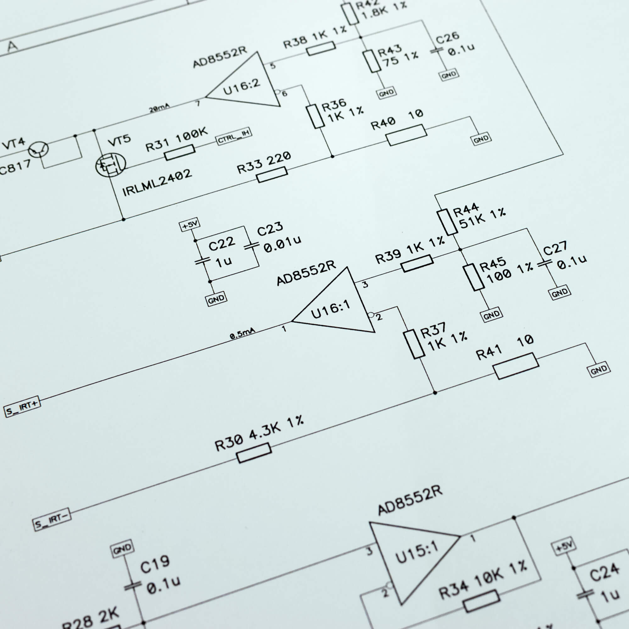
For verifying mixed-signal circuits, modeling the operation of analog and digital signals using design languages such as Verilog-AMS and reproducing the overall behavior is an effective method. This allows for the detection of interference and performance degradation risks before implementation. Furthermore, using symbolic models allows for analytical evaluation of stability and sensitivity, enabling early determination of the design direction. Performing these verifications before physical design reduces the number of prototypes and shortens the development period.
Crosstalk and Power Management
Crosstalk occurs due to adjacent signal paths and parasitic elements on the board, causing malfunctions and performance degradation. To prevent this, critical signal paths are isolated and shielding is applied as needed. In power management, multi-stage decoupling and power domain isolation are effective in suppressing noise caused by load fluctuations and switching. Especially for analog circuits, providing a clean power supply ensures measurement accuracy and stability.
Basic Considerations for PCB Layout
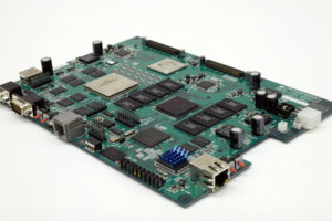
In PCB design, the most important thing is to ensure that the isolation and power plan established in silicon are not compromised during the PCB layout stage. Analog/digital placement separation, securing continuous ground planes, short return paths, appropriate decoupling, characteristic impedance matching, minimizing clock and reference paths, and power distribution planning for each power domain are systematically applied. Based on product conditions (temperature, EMI/EMC, mechanical constraints), extra board space/clearance is reserved for probing and component repositioning during the prototyping phase, resulting in a design that can withstand mass production variations.
Domain Isolation
Analog and digital are clearly zoned, and highly sensitive circuits (ADC, reference, front-end) are protected from noise sources (high-speed I/O, switching power supplies, clock) with distance and shielding. Simultaneously mapping signal flow and return paths between blocks and keeping loop area small is effective. Prioritize component placement based on input/output proximity, the shortest possible reference and sensor paths, and straight power supply routing. Ensure access to test points and fixtures from the initial stages. This facilitates root cause analysis and reduces redesign rework.
Grounding
Use a continuous, wide ground plane as the reference, avoiding unnecessary slots and interruptions. At high frequencies, return current passes directly beneath the signal, so interruptions lead to detours and increased radiation. Carefully consider complete separation of analog and digital grounds, and strictly enforce rules to prevent critical signals from crossing interruptions. Increasing via stitching and ground via density in key areas, and placing low-ESL decoupling near power supply pins, can consistently reduce return impedance.
Wiring and Power Supply
Design high-speed signals with characteristic impedance, and ensure consistent spacing, length, and layer configuration for differential pairs. Clock and reference lines should be kept as short as possible, distanced from other aggressors, and shielded or guarded as needed. Power supplies should utilize multiple capacitors of varying values, placed close together to cover different frequency bands, minimizing power supply loops. Separating power supply domains for analog and digital circuits, and clearly defining the roles of LDOs and switching circuits, reduces power supply noise. IR drop and temperature rise should also be evaluated in parallel to ensure design margins.
Summary
Key Points of Mixed-Signal IC Design
In mixed-signal IC design, understanding the operating principles and roles of key components such as ADCs, DACs, PLLs, power management circuits, and RF CMOS is fundamental. Design challenges include noise interference from high-speed digital switching, crosstalk due to close wiring, and power supply quality degradation. Effective countermeasures include zoning analog and digital circuits, controlled ground design for return paths, and impedance matching of signal paths. Combining these measures enables stable performance during mass production and quality assurance from the initial design stage.
Future Trends and Technological Developments (AI-Assisted Design, Chiplets)
The integration of EDA tools and AI technology is rapidly advancing the automation of circuit placement and parameter optimization. AI, in particular, proposes optimal zoning and routing from a vast number of design patterns, achieving both reduced design time and improved performance. Furthermore, chiplet technology is attracting attention for its method of manufacturing analog and digital components on separate dies using optimal processes and connecting them at high density within the package. This increases the freedom of process selection and contributes to improved cost efficiency and reliability.
Recommended Resources for Designers (Tools, Literature)
To deepen your understanding of mixed-signal ICs, experience with mixed-signal circuit modeling using Verilog-AMS and stability evaluation using symbolic analysis tools is effective. Some manufacturers provide application notes that explain implementation challenges and solutions with concrete examples, directly applicable to practical work. Furthermore, reading foundational texts on analog/digital mixed-signal design as well as PCB layout technology will broaden the scope of design considerations. This knowledge is useful from the early stages of design.
FeRAM-based Analog ASIC Design and Development Services