FeRAM Features, Principles, and Basic Operation
FeRAM (Ferroelectric Random Access Memory) is a type of non-volatile memory that also incorporates the advantages of volatile memory in addition to non-volatility, which allows data to be retained even when the power is turned off. It also offers high rewrite endurance and high-speed write performance. The following article explains the features, principles, and basic operation of FeRAM.
Features of FeRAM
Features of FeRAM FeRAM (Ferroelectric Random Access Memory) is a type of non-volatile memory that combines the advantages of volatile memory in addition to the typical benefits of non-volatile memory, such as retention without power (non-volatility) and low power consumption. It also provides high rewrite endurance and fast write capability.
FeRAM is characterized by these key features. Table 1 shows a comparison of FeRAM eith other memory technologies. FeRAM uses ferroelectric materials as its memory element, and advances in process technology have enabled rewrite endurance of up to 100 trillion (1014) cycles as well as operation at high temperatures up to 125°C.

Principles of FeRAM
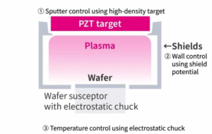
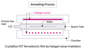
FeRAM uses PZT (lead zirconate titanate) as its ferroelectric material. Figure 1 shows the crystallyne structure of PZT. A key characteristic of PZT crystals is that polarization occurs when voltage is applied (due to the displacement of Zr/Ti ions within the crystal structure). This polarization remains even after the applied voltage is removed because the Zr/Ti ions have two stable states depending on the direction of the electric field, and these two stable states are used to represent “0” and “1” data in non-volatile memory.
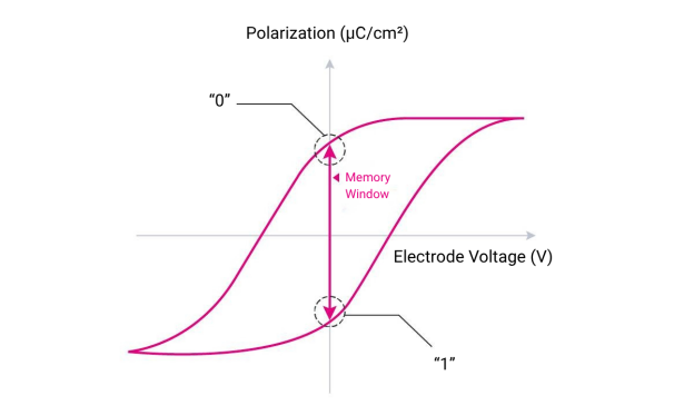
Figure 2 shows the voltage dependence of polarization in PZT crystals. The polarization exhibits a hysteresis loop, with two remnant polarization states at 0 V, which are used to represent “0” and “1” data. Since the movement of Zr/Ti ions within the crystal does not cause physical degradation, the memory element achieves high rewrite endurance. In addition, switching between “0” and “1”is achieved by reversing the direction of the polarization direction through the applied electric field, enabling “overwrite capability” as described Table 1.
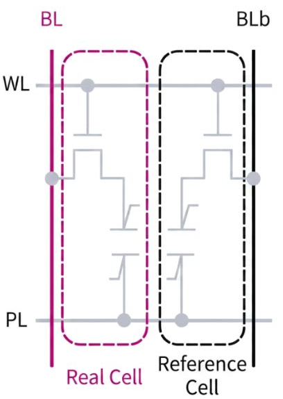
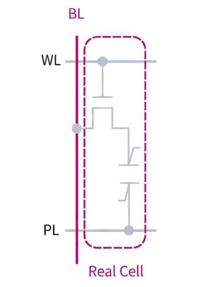
The 2T2C type FeRAM operates using two capacitors with complementary polarizing states. During read operation, the voltages of the bit line (BL) and its complementary bit line (BLb) are compared. For example, when voltage of BL is higher than that of BLb, the stored data is determined as “1,” otherwise it is “0.” Because two capacitors are used to stabilize data retention, this structure is suitable for products requiring high reliability, such as automotive applications.
The 1T1C type FeRAM operates using a single capacitor per cell. During read operation, the voltage of the BL is compared with a voltage generated by a separated circuit are compared. For example, when the reference voltage is higher than the BL voltage, the data is determined to be “1”, otherwise it is “0.” Since cell size is approximately half that of the 2T2C structure, this type is suitable for high-density memory application.
Basic Operation of FeRAM
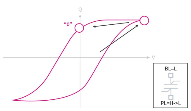
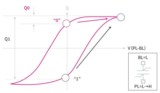
Figure 6 shows the read operation for a memory cell. The electrode of the ferroelectric capacitor connected to the BL is set to a low voltage level (L), while the electrode connected to the PL is raised to a high voltage level (H) from L (BL = L, PL = L → H). When the PL voltage level transitions from L to H, the amount of charge released from the ferroelectric capacitor differs depending on the initial polarization state, as indicated by “Q0” or “Q1” in Figure 6. This difference results in in voltage difference of the BL. A sense amplifier detects the BL-voltage difference and determines whether the stored data is “0” or “1.”
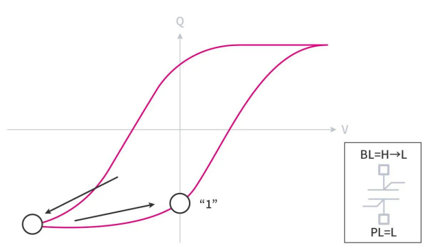
Figures 7 and 8 show the write operations of “0” and “1”, respectively. To write “0”, the electrode connected to the BL of the ferroelectric capacitor is set to L, while another side of electrode connected to the PL is raised to H from L (BL = L, PL = H). Afterward, the PL returns to L, allowing the cell to remain in a standby state with retaining “0.” To write “1”, the electrode connected to the BL is raised to H, while the electrode connected to the PL is set to L (BL = H, PL = L). Afterward, the BL returns to L, and the cell remains in standby state with retaining the “1.”